2025/11/07

Why go solderless at the board edge
Above ~50 GHz, little variations stop being little. A thick or uneven solder fillet, a small misalignment at the edge, or a rough board cut can nudge impedance and show up as ripple. A solderless end-launch removes the fillet from the RF path and uses a precision 0.127 mm pin that meets the PCB trace directly. It is also serviceable: you can mount, inspect, and remount without rework heat. The net effect is fewer variables at the transition and more repeatable S-parameters over multiple builds.
The two parts we are talking about
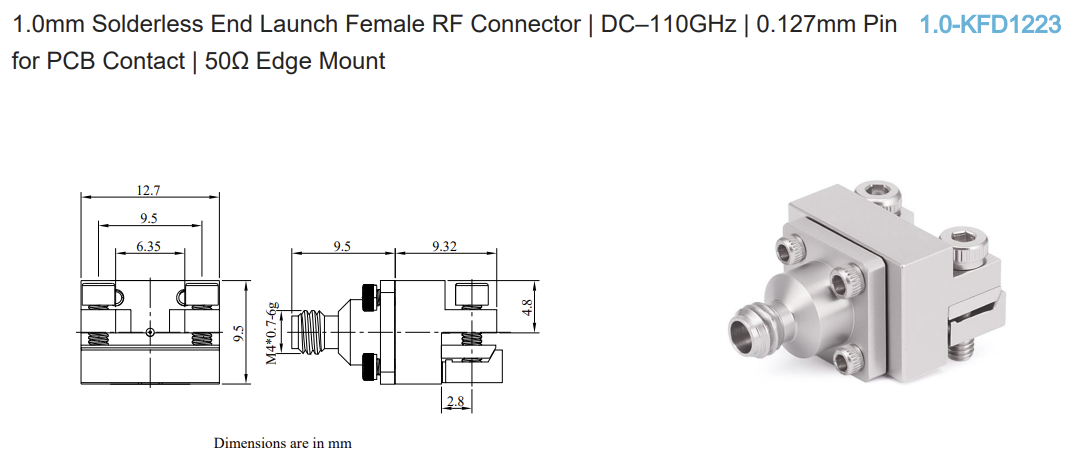
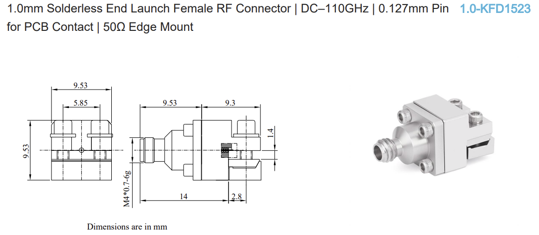
Both 1.0-KFD1223 and 1.0-KFD1523 are 1.0 mm female, 50 Ω, edge-mount, solderless connectors specified from DC to 110 GHz with low VSWR (≤ 1.45) when they are used with a proper launch layout. Each uses a stainless-steel body for mechanical stability and the same 0.127 mm pin size for the PCB contact. Electrically, they aim at the same target: a clean, controlled transition off the board into a 1.0 mm interface.
Where they differ is how you mount them and how they meet your mechanics:
 1.0-KFD1223

1.0-KFD1523
Same RF intent, different mechanical paths: choose the one that fits your panel/fixture and your layout workflow.
What “good” looks like at 110 GHz
A good result starts with a controlled-impedance trace meeting the 1.0 mm pin smoothly at the board edge. Keep the edge clean and straight, follow the land pattern and keep-outs, and fence the ground with vias at the spacing the footprint expects. Then, verify S11 across frequency on a calibrated setup rather than relying on a single number. If the trace is not behaving, the usual culprits are edge roughness, stack-up drift (dielectric height or copper thickness), gaps or stubs near the launch, or a slight skew introduced during installation. The solderless approach does not “fix” an RF geometry, but it makes it easier to refine without thermal cycles.
Where do you see them
You will see these 1.0 mm end-launches on eval boards and fixtures in test & measurement, in RF communications R&D pushing well past 70 GHz, and in aerospace/defense labs where mechanical stability matters as much as electrical repeatability. They are also common in industrial research antenna arrays, packaging studies, and other mmWave experiments. They are used as well in high-speed data transmission work, including signal-integrity fixtures and characterization setups for multi-gigabit links where board-edge launches must preserve bandwidth and minimize reflections that affect the eye diagram. In the semiconductor domain, they support wafer-level and package-level characterization and RFIC and mmWave front-end evaluation, where repeatable and serviceable launches help reduce variability across probes, sockets, and test vehicles.
The shared theme: fast learning loops and stable, serviceable launches.
What to expect on the bench
Calibrate for the band you care about, mount and torque the connector per spec, then check S11 at the launch first. A quick S21 through your intended path will show the cumulative impact of the transition. Document with a plot and a photo; it saves time when you iterate. If results drift, look first at mechanics, edge prep, via fencing, and alignment, before you chase deeper effects.
Why these two, specifically
Most teams working at 110 GHz want two things: a dependable 1.0 mm transition that behaves on a real board and a connector they can service without reflow. KFD1223 gives you flange mounting with a field-replaceable contact and a passivated body; KFD1523 gives you a direct end-launch with PCB termination and tri-metal plating. Pick the mechanical style that fits your fixture, panel, and assembly flow, the RF goal is the same.
Availability and support
Both parts have completed validation and are entering production. General availability will open soon. If you are planning a design-in, contact us to review your launch notes and schedule the earliest delivery window.
Specs overview
1.0 mm female, solderless, edge-mount, DC–110 GHz, 50 Ω, VSWR ≤ 1.45 (with proper launch), 0.127 mm pin, stainless-steel body.


